
Getting My Ceiling Fan into Home Assistant, with AI's Help
How Claude Code and Codex helped me connect my ceiling fan to Home Assistant with an ESP32 BLE bridge, a few wrong turns, and a custom 3D-printed enclosure.
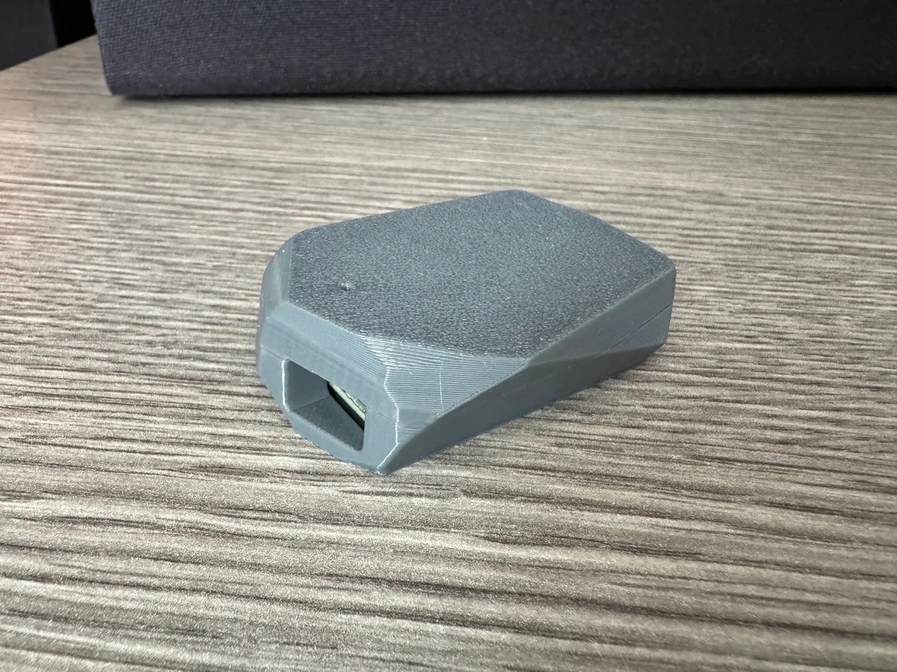
My living room ceiling light was the one light I could not bring into Home Assistant. It bothered me more than it probably should have.
Over the years, I have tried to make most things in my house controllable through Home Assistant. I have already written about the automations I keep in Node-RED and how I use Home Assistant for parental controls. Once you get used to lights following the evening routine or responding to a voice command, the one that still needs its own remote becomes quite noticeable.
Last year, I replaced the living room light with a ceiling light that has an integrated fan. It came with a remote, and I assumed that would make integration straightforward. I already had a Broadlink RM3 for infrared devices. I expected to teach it the commands and carry on.
After installing the light, I discovered that the remote was not infrared. I put the problem aside for a while, but every evening the light was still outside the rest of the system.
Buying the wrong solution
Recently, I watched Ambient Object, a YouTube series about building a physical device with Claude. That gave me a reason to come back to the ceiling fan. I had mostly been using coding agents for software; perhaps I could use the same approach to solve this too.
I started with a simple question to Claude Code: how could I control this thing?
Claude suggested that the remote probably used radio and recommended replacing my Broadlink RM3 with an RM4 Pro, which also supports RF control. It sounded like a reasonably inexpensive solution, so I ordered one.
When it arrived, I found the detail we should have checked before buying it. The RF bands supported by the Broadlink did not include the 2.4 GHz band used by my remote.
I had replaced a working device and still could not control the light.
The frequency did not tell us enough
Early on, Claude had also suggested checking whether the remote used Bluetooth. I installed a scanner app on my iPhone, tried it, and saw nothing useful. At the time, that seemed to move us away from Bluetooth, although the test had not actually ruled it out.
We then explored ways to work with the remote’s 2.4 GHz radio. This is where my understanding was still fuzzy: I was associating that frequency with Wi-Fi. But a frequency band alone does not identify the protocol. In this case, that distinction would cost me another detour.
Among the options Claude proposed was building a bridge with an ESP32 and an external radio module. It was the more involved route, but I have development experience, and the idea of building my own device appealed to me.
I let Claude guide me through buying the components on Amazon. For the parts I was looking at, AliExpress did not seem to offer enough of a saving to make a difference. The external module we chose was an nRF24L01+, a 2.4 GHz radio module, rather than a Wi-Fi module.
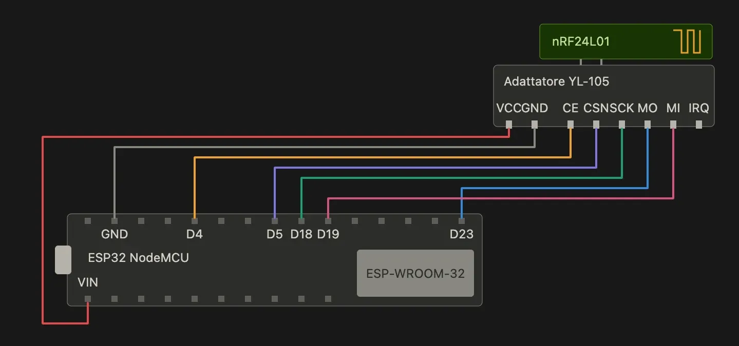
The wiring plan for the external-radio approach we later abandoned. The final BLE bridge did not need this module or its wiring.
While waiting for the parts, I also had an enclosure designed for 3D printing. If this was going to live in the house, I wanted it to have an actual shape instead of leaving loose wires on a shelf.
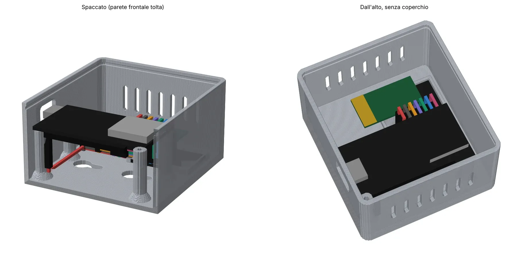
The first enclosure design made room for the board, the external radio module, and their wiring.
Getting to a working bridge
Once the parts arrived, I assembled them and switched to Codex for the firmware work. We started trying to make the hardware do what we needed.
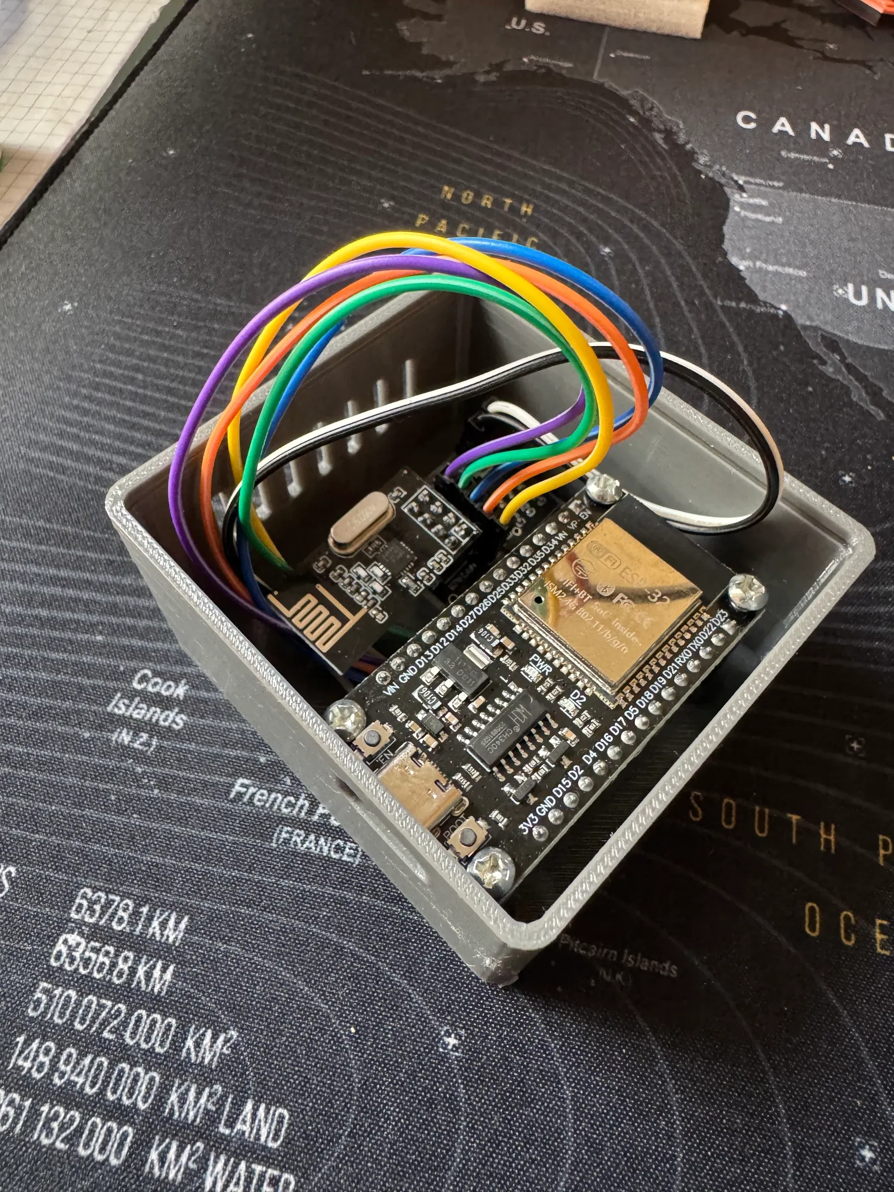
The assembled prototype, before we moved away from the external radio.
After several attempts, we established that the remote used Bluetooth Low Energy commands. That brought us back to a possibility we had considered near the beginning and then set aside after my phone scan.
The external radio components I had just bought were unnecessary for the solution we eventually used. An ESP32 board I already had at home turned out to be useful instead.
The board I had bought was newer, with USB-C and pin headers already soldered on. Even with nothing connected to those pins, they would have needed extra vertical space inside the case. The board I had at home, probably an older generation, had no headers attached. With no external radio module left to connect, I could use it as it was and design a much smaller, lower enclosure that would take up less space in the house.
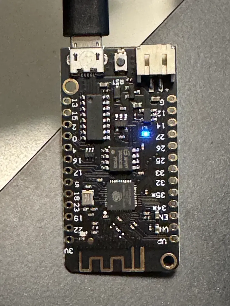
We tried our own approaches, then searched GitHub for existing projects until we found FanBridge by Cleobury. That was the firmware we adapted for the working bridge. Finding it was a substantial part of getting this finished. The agents helped me get it running on the board I already had.
I ended up with a small bridge, complete with a web interface, that could control the living room light. From there, integrating it with Home Assistant was straightforward. I have tested that integration several times and already used it successfully. The living room light could finally take part in the same system as the rest of the house.
What the bridge is doing
The remote sends Bluetooth Low Energy advertising packets in the FanLamp format. It does not need to establish a Bluetooth connection with the light. FanBridge learns the remote’s identity and protocol variant, then broadcasts compatible commands from the ESP32. Its protocol documentation explains the packet formats.
The original FanBridge targets an ESP32-S3 and includes Matter support. Our port uses a classic ESP32 with NimBLE-Arduino, a local web interface, and HTTP commands. Matter is disabled in this version. Wi-Fi connects the bridge to the home network; BLE carries the commands to the ceiling light. There is no external radio module involved.
For my non-dimmable light, the command we use is a toggle. It does not report the light’s actual state back to Home Assistant. I have verified the light control; the firmware’s other fan and light features should not be taken as tested on my unit.
There is more open-source work behind this than I understood while we were trying to get it running. FanBridge credits NicoIIT’s ha-ble-adv for the FanLamp protocol information and constants. During the earlier investigation, we also used the encoder from framarche83’s Philips Bliss project. That experiment did not produce visible control on my unit; FanBridge was the route that worked. These projects are distributed under the MIT license, and their attribution is preserved in my firmware repository.
Giving it a place in the house
Of course, I was not going to stop at an exposed ESP32 sitting somewhere in the living room.
The hardware had changed, so I had a new enclosure designed around the board we actually used. This time I wanted it to look a little more intentional too. I printed it in 3D and put the bridge inside.
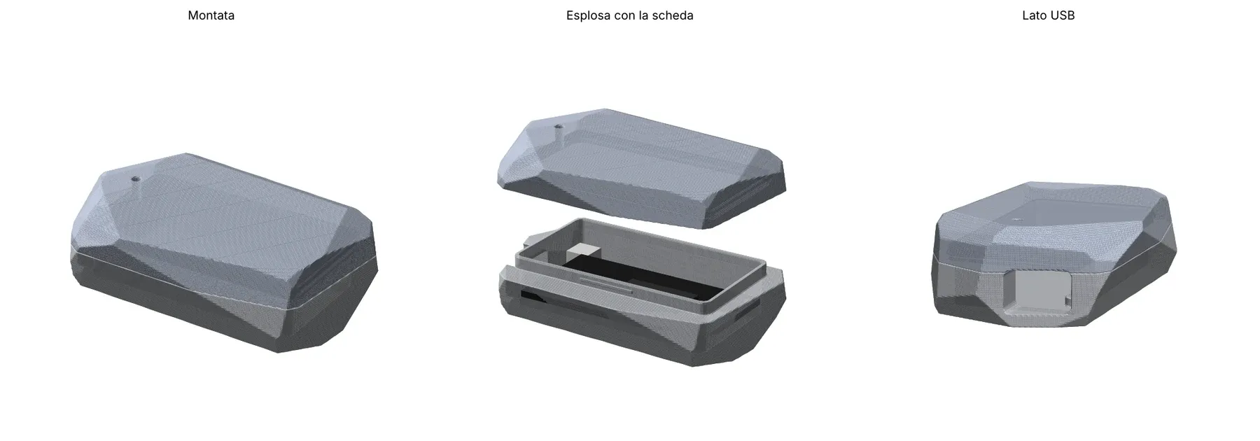
The enclosure design, shown assembled, with the lid lifted to reveal the board, and from the USB side.
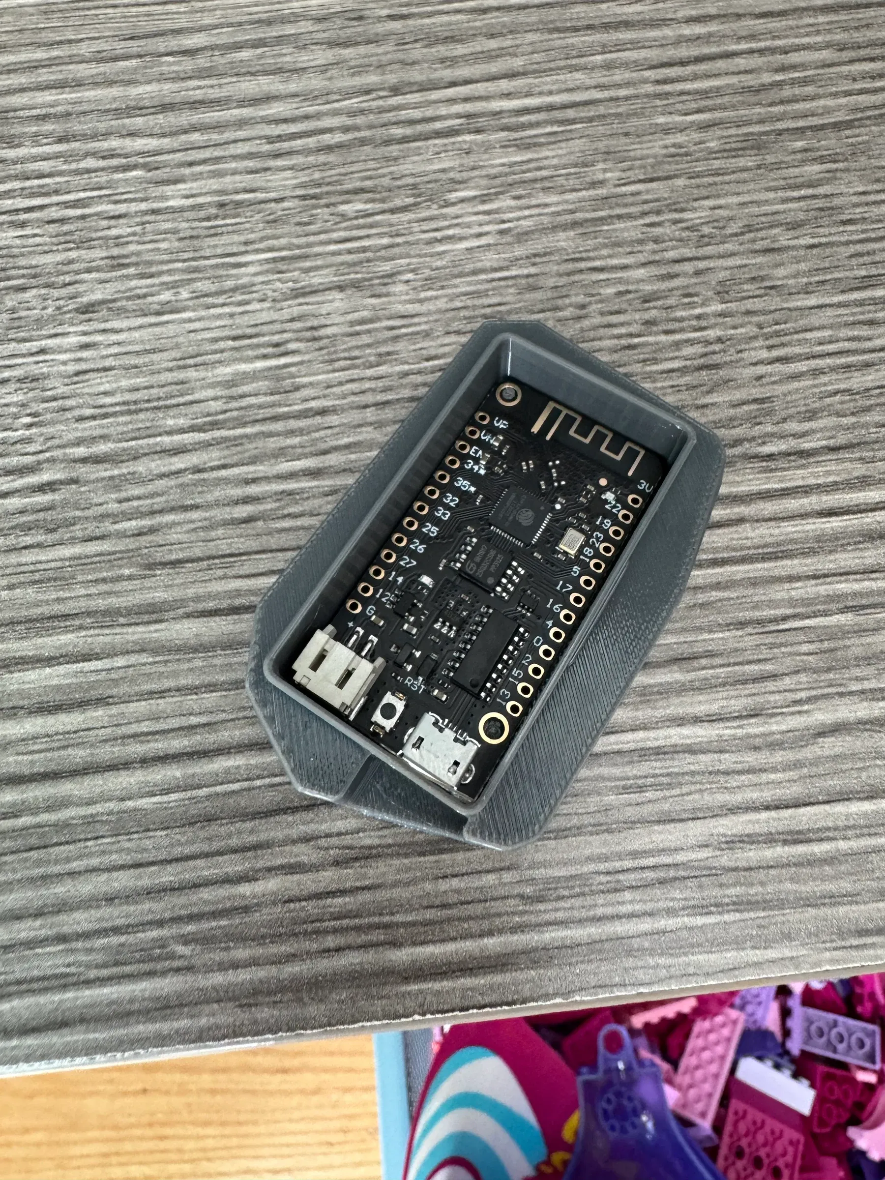
The board inside the printed enclosure.
That part of the experience matters to me. I started with a light that did not fit into my automations and finished with a physical object I had assembled, configured, and housed myself. The firmware and the enclosure were both things I could ask an agent to help me work through.
How much of the work did I have to do?
Very little of my own effort went into writing firmware or working out every setup step. Claude Code and Codex guided me through choosing parts, assembling the device, trying software, and designing something I could print.
I still bought the parts, connected them, ran the tests, and checked whether the light actually responded. My development experience helped me follow the process and keep going when an approach failed. I would not assume that someone starting from zero would have exactly the same experience.
And there were wrong turns. I bought a Broadlink that could not solve this problem. I bought radio components that the final bridge did not need. We also came back to Bluetooth after an early test had led us away from it. Those are part of what happened, alongside the working result.
Taking an idea into the physical world
What stays with me is how useful these tools are becoming for the steps between an idea and something I can put in my house.
Until now, when I needed to design something for 3D printing, I used Tinkercad because my modeling skills were limited. For this enclosure, I described what I needed and supplied a few measurements. The agent handled the modeling and proposed several designs for me to choose from. I could spend my attention on whether I liked the object and whether it would fit the board.
I had already used this approach for the printer’s own setup. I supplied a photograph of the attic space where I wanted to put it, and the agent created renderings I could navigate to explore different arrangements. I chose one, and it also helped me work out how to build a small storage cabinet for the parts.
That makes me want to experiment more. I can now try ideas that would previously have stopped at the edge of my design skills, whether that means an enclosure for a board or a place to keep the printer and its supplies. If you have a small project you have been putting off for similar reasons, I would encourage you to give it a try. Start with what you need, take a few measurements, and see what you can make with some help.
References
- Ambient Object, the YouTube series that inspired this project.
- Cleobury/FanBridge, the firmware adapted for my working bridge; based on commit 52b5b7a.
- FanBridge protocol documentation, covering the BLE advertising packet formats.
- NicoIIT/ha-ble-adv, credited by FanBridge for the FanLamp protocol information and constants.
- framarche83/philips-bliss-esphome-remote, used during the earlier protocol investigation.
- Home Assistant, the home automation platform I use.
- Bluetooth Low Energy, background on the wireless technology used in the final solution.
Share